
- Forum
- Geiger counter discussions
- Homebrew counters, electronic design and building
- DIY Gamma Spectrometer - help needed
DIY Gamma Spectrometer - help needed
4 years 8 months ago - 4 years 7 months ago #4503
by Simomax
Hello all!
I want to build a DIY gamma spectrometer but need some help. I have acquired a rather nice Mini-Instruments Scintillation Meter Type 5.40 and would like to use this in a spectrometer setup. It's probably easier to explain what I want to achieve than delving into the nuts and bolts of it all at this point. So what I want to do is connect my scintillation meter to the audio input of a PC and run something like Theremino on the PC to record and chart the results. To accomplish this I would like to modify the scintillation meter to give a pulse output to a PC sound card input (+-1Vpp). I thought about just splitting off the speaker direct into the sound card with some electronics to make the levels compatible but I don't think that would work as it is my understanding that the circuitry for making the speaker click makes the pulse longer and will give something of a square wave to the speaker at a certain voltage and it is my understanding that either the pulse time and/or amplitude is what is necessary to determine the KeV for different isotopes, thus I would need to split out of the counter circuit somewhere before the speaker and meter circuits. Unfortunately I can't find a circuit diagram for my scintillation meter, or any others for other Mini-Instruments meters and I haven't had, nor really got the time right now to reverse engineer the circuit. I may be my only option but I reckoned I'd ask the hive-mind first.
This is something I really would like to do and would publish my findings/how to so others can also do the same. There are quite a few Mini-Instruments scintillation meters knocking about on the internet from time to time and I think this would be a great thing to use as the detector. I have all the parts needed to accomplish this except a way to get the pulses from the meter to the PC, which is where I need the help. I know you can buy 'boxes' for this purpose that have a HV PSU and detection circuitry where by I simply hook up my scintillation probe to it and plug it in to the PC but I don't want to spend £100+ on one and would much rather build and share a homebrew solution.
What I have so far for this project is:
- Mini-Instruments Scintillation Meter Type 5.40 (an older version of the Mini 900 (MFG016 Type 900/44A from this page: https://www.thermofisher.com/order/catalog/product/MFG011). This has already had a mains power conversion so is ideal for being left on for lengths of time.
- A large amount of old lead pipes/lead flashing and other bits of lead to melt into blocks to offer a shield for the detector.
- A large amount of radioactive samples for testing (Americium, Thorium, Tritium (gas), Uranium in many forms (glass, ore, depleted, UO3, UO2 (yellowcake)), Radium.
- A Lutetium Lu176 Calibration Check Source for Gamma Spectroscopy (on it's way as I write this).
- A dedicated PC (old laptop)
The only thing I don't have is a way to connect the scintillation meter to the PC so any help whatsoever even if just pointing to places I can research would be very much appreciated.
Cheers!
Simon
Last edit: 4 years 7 months ago by Simomax.
Please Log in or Create an account to join the conversation.
4 years 8 months ago #4504
by mw0uzo
Replied by mw0uzo on topic DIY Gamma Spectrometer - help needed
Sounds like a great project, I will follow it with interest! I know RH Electronics has done lots of work in this area:
https://rhelectronics.net/store/diy-pic18-mca-kit-for-gamma-spectroscopy.html
https://rhelectronics.net/store/diy-pic18-mca-kit-for-gamma-spectroscopy.html
The following user(s) said Thank You: Simomax
Please Log in or Create an account to join the conversation.
4 years 7 months ago - 4 years 7 months ago #4556
by Simomax
Replied by Simomax on topic DIY Gamma Spectrometer - help needed
Thanks Dan. That is like the 'boxes' I have seen online that basically replace the counter itself and you just connect the photomultiplier tube to and connect up to a PC. I don't want to go down that route for a couple of reasons, one being cost of the unit (not that I can't afford it, I'm just tight!) and the other being that I would probably never be happy unless I knew that the interface (box) was configured properly for the photomultiplier tube. I would rather modify the original circuit by adding an output for PC sound card.
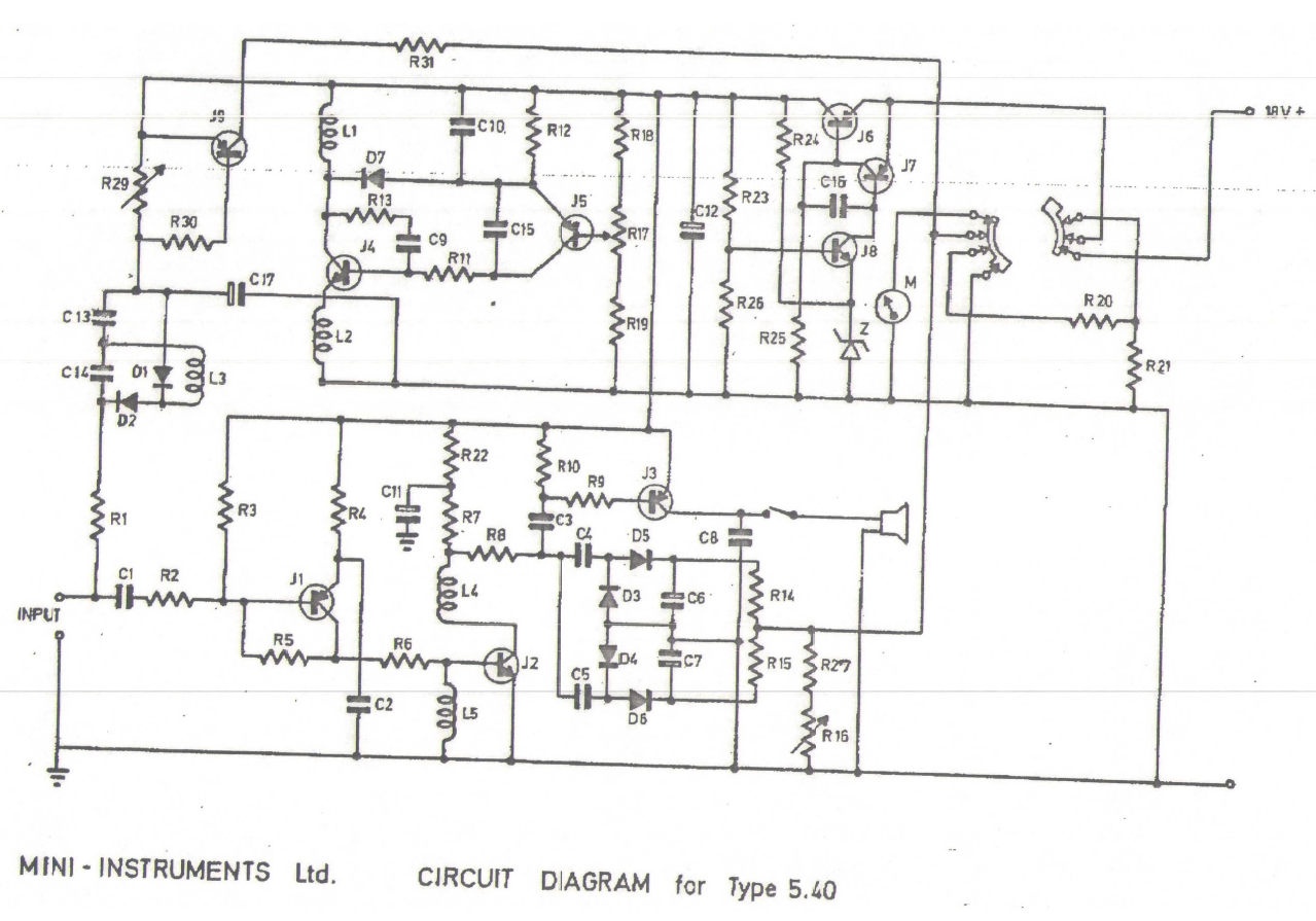
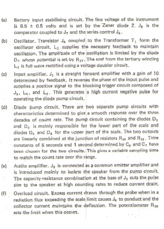
As it happens I had just taken my meter to bits in lieu of reverse engineering the board (which I didn't really want to do) but thought I would have one last search on the internet for any additional info. I'm looking for the circuit diagram more than anything. Anyway, luckily I managed to find the original instructions for my meter that also applies similarly to the other 5.10 model (which I also have - has a GM tube a, b & y) and ever so very luckily it contains the circuit diagram for both models! (Edit: After a light peruse of the document it doesn't contain the 5.10 manual although the circuit is almost identical.. Still..) Winner winner chicken dinner!
Finding that has more than halved the work I thought necessary to make this project a thing! If interested the manual is here (all 474 pages of it!?!): https://archive.org/details/MiniInstruments/page/n25 It can also be downloaded as PDF: https://ia800900.us.archive.org/23/items/MiniInstruments/Mini%20Instruments%20Mini%20Monitor%20%20900%20and%205.40%20series%20geiger%20counter%20manuals%20etc.pdf
After a very brief scan through random pages it looks to have some good info in. Not just about the meter but about reading radiation and other stuff. Lots of technical stuff. You can't see me smiling but I'm super happy to find this!
Last edit: 4 years 7 months ago by Simomax.
Please Log in or Create an account to join the conversation.
4 years 7 months ago - 2 years 4 months ago #4557
by Simomax
Replied by Simomax on topic DIY Gamma Spectrometer - help needed
After a quick look over the circuit and reading the circuit description I reckon I could tap off somewhere right after J1 and use (make) a small amp circuit to the PC sound card input. Time to get the scope out and have a look at it in operation. This really is the info I have been looking for. If I manage to get it all working as a spectrometer I will most certainly write a small 'how to' for other's to follow. It's one thing being able to detect radionuclides but a completely different animal being able to differentiate between radionuclides.
Attachments:
Last edit: 2 years 4 months ago by Simomax.
Please Log in or Create an account to join the conversation.
4 years 7 months ago - 4 years 7 months ago #4593
by Simomax
Replied by Simomax on topic DIY Gamma Spectrometer using Mini-Instruments 5.40 Scintillator
A quick update:
I have had a bit of a probe about with a scope on this and I'm 95% certain what I want to achieve can be done. I'm reckoning to tap off right between C1 and R2 where they connect and make a small inverting amp circuit to connect to the PC soundcard. I have also been doing more research and the Theremino MCA software comes with a lot of documentation and is suggested the signal needs to be conditioned also. Mostly in the form of filters.
So next stage is to build a little amp circuit and test, then look at filtering. Then all being well it should just be a matter of learning the software and making sure all the settings are good for sampling from the scintillator. More to come soon!
I have changed the thread title (from DIY Gamma Spectrometer - Help Needed) as I'm not so much looking for help now. But please chip in if you have any information or ideas!
Last edit: 4 years 7 months ago by Simomax.
The following user(s) said Thank You: mw0uzo
Please Log in or Create an account to join the conversation.
4 years 7 months ago #4762
by Simomax
Replied by Simomax on topic DIY Gamma Spectrometer using Mini-Instruments 5.40 Scintillator
I have decided to cancel this project, or at least put it indefinitely on hold. It appears the probe I have isn't suitable for gamma spectroscopy as it is suited for the lower energy range. On another thread RHStation said this:
I'm going to revisit this at some point but not using my 5.40 scintillation meter and I'll probably look at either building my own probe or see if I can obtain one that is more fit for purpose in the future.
Simon, 32x2.5mm crystal will not be good for spectroscopy in range of 26keV-3000keV. 5-44A probe made rather for low energy detection of medical isotopes or some XRF
For gamma spectroscopy you need crystal geometry like 25x25mm, 30x30mm, 40x40mm, 30x50mm, 63x63mm or similar ratio. Equal ratio 1:1 works better. And PMT photocathode diameter should be equal or larger than crystal window.
I'm going to revisit this at some point but not using my 5.40 scintillation meter and I'll probably look at either building my own probe or see if I can obtain one that is more fit for purpose in the future.
Please Log in or Create an account to join the conversation.
Moderators: Gamma-Man
- Forum
- Geiger counter discussions
- Homebrew counters, electronic design and building
- DIY Gamma Spectrometer - help needed
Time to create page: 0.201 seconds