
- Forum
- General chat
- General discussion
- Any radmon experts here? My unit has failed after water ingress
Any radmon experts here? My unit has failed after water ingress

2 years 9 months ago - 2 years 9 months ago #6613
by nzoomed
Replied by nzoomed on topic Any radmon experts here? My unit has failed after water ingress
Didn't realise that part was obsolete, I'm sure I saw some on ebay.
Anyway, just looked at my board and it's got the STX13005 installed, so that must be what he is putting in the kits nowadays.
https://www.datasheetbank.com/datasheet-download/643141/1/ST-Microelectronics/X13005?v=2005
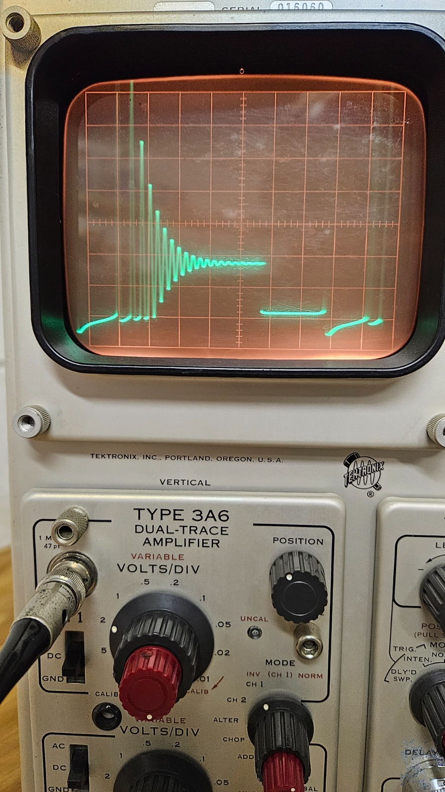
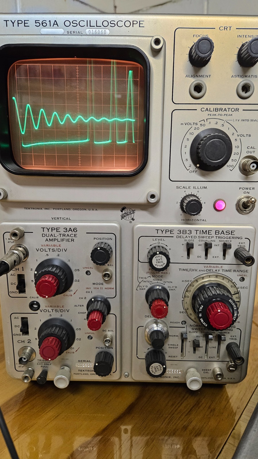
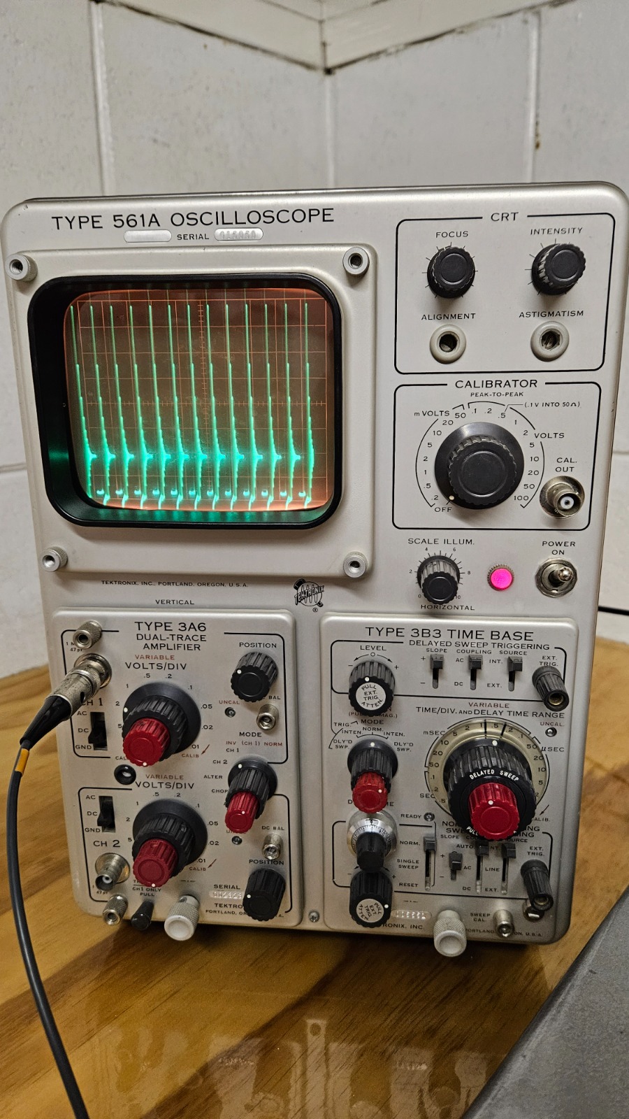
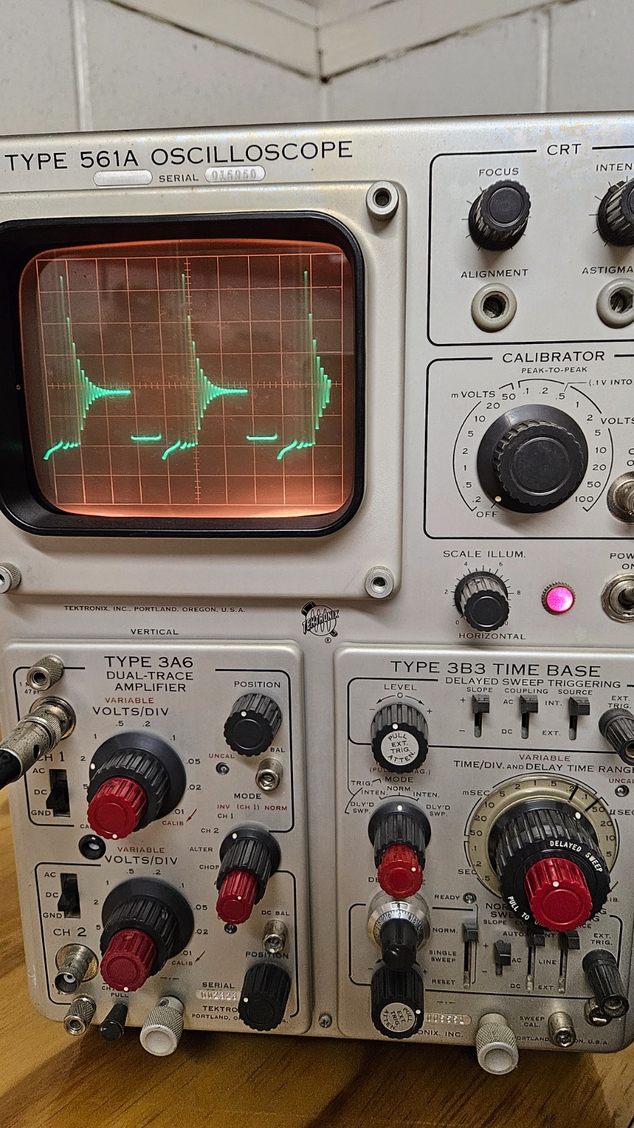
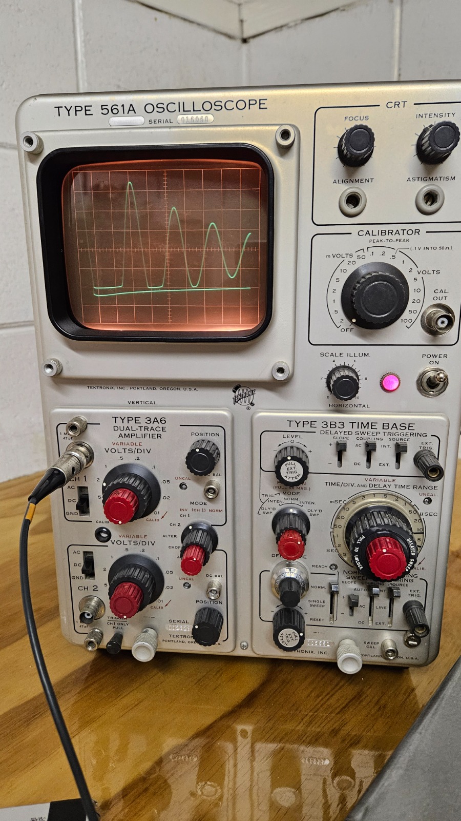
Have scoped the transistors collector, am getting a signal, but seems to be unbalanced and not a clean waveform. Is this what I should expect?
Take note of the time divisions in each photo, I played around on the scope to find what gave the most detail.
Edit:
After probing around with the meter and scooe it appears to be working now! Dry joint perhaps?
I dont know if I'm getting the right voltage, but it is counting.
I know the guide says to use the string of resistors to make measurements, i get about 25.8v on the meter doing this which if my calculations are correct its about 250v or 130v on my scope which is about what the meter reads with no resistor string.
the unit tells me it is set to 404v so I have no idea what the true voltage is, but I'm not.getting any shock when touching the terminals.
Anyway, just looked at my board and it's got the STX13005 installed, so that must be what he is putting in the kits nowadays.
https://www.datasheetbank.com/datasheet-download/643141/1/ST-Microelectronics/X13005?v=2005
Have scoped the transistors collector, am getting a signal, but seems to be unbalanced and not a clean waveform. Is this what I should expect?
Take note of the time divisions in each photo, I played around on the scope to find what gave the most detail.
Edit:
After probing around with the meter and scooe it appears to be working now! Dry joint perhaps?
I dont know if I'm getting the right voltage, but it is counting.
I know the guide says to use the string of resistors to make measurements, i get about 25.8v on the meter doing this which if my calculations are correct its about 250v or 130v on my scope which is about what the meter reads with no resistor string.
the unit tells me it is set to 404v so I have no idea what the true voltage is, but I'm not.getting any shock when touching the terminals.
Last edit: 2 years 9 months ago by nzoomed.
Please Log in or Create an account to join the conversation.
2 years 9 months ago #6614
by Simomax
Replied by Simomax on topic Any radmon experts here? My unit has failed after water ingress
The scope traces look somewhat like a boost circuit. It's not easy to read the waveforms as the inductor clamps it to VCC and the transistor is switching ground. The ringing effect seen is caused by the magnetic flux in the inductor collapsing when the transistor is switched off. It looks OK to me. Some info on boost circuits here:
https://en.wikipedia.org/wiki/Boost_converter
I doubt dry joints. They are pretty rare these days and were most common in old vacuum tube devices and CRT TVs. They were caused by the high voltage and frequency breaking down the solder. Solder and other materials for components have come on in leaps and bounds since then so they are pretty rare. Your counter wouldn't have the current to start affecting the solder joints. A bad solder joint on the other hand is a different animal. Assuming you bought the counter as a kit and built it and soldered it yourself, you tell us.

Not sure about the voltage to the tube. I use a 1 gig ohm / 1 meg ohm voltage divider to read the voltage at the tube. It works well and gives a fairly accurate reading when used with a 20 meg ohm meter. I can check on my GK Radmon later today and see what I get at the tube with just a meter. Did you alter the voltage pot? If not, then I wouldn't worry about it. If you did, you should adjust to get the voltage as close to the desired as possible. Too little and you are going to miss out on counts, too much and it could avalanche.
I doubt dry joints. They are pretty rare these days and were most common in old vacuum tube devices and CRT TVs. They were caused by the high voltage and frequency breaking down the solder. Solder and other materials for components have come on in leaps and bounds since then so they are pretty rare. Your counter wouldn't have the current to start affecting the solder joints. A bad solder joint on the other hand is a different animal. Assuming you bought the counter as a kit and built it and soldered it yourself, you tell us.
Not sure about the voltage to the tube. I use a 1 gig ohm / 1 meg ohm voltage divider to read the voltage at the tube. It works well and gives a fairly accurate reading when used with a 20 meg ohm meter. I can check on my GK Radmon later today and see what I get at the tube with just a meter. Did you alter the voltage pot? If not, then I wouldn't worry about it. If you did, you should adjust to get the voltage as close to the desired as possible. Too little and you are going to miss out on counts, too much and it could avalanche.
Please Log in or Create an account to join the conversation.
2 years 9 months ago #6616
by Simomax
Replied by Simomax on topic Any radmon experts here? My unit has failed after water ingress
I have just checked my GK Radmon basic with my meter and I'm getting exactly 400v at the tube connectors, which is interesting as my meter isn't pulling the voltage down. My meter must be better than I thought!
 Or the HV PSU has enough current to overcome the meter burden.
Please Log in or Create an account to join the conversation.
2 years 9 months ago - 2 years 9 months ago #6617
by nzoomed
Replied by nzoomed on topic Any radmon experts here? My unit has failed after water ingress
I should clarify a few things first.
Yes I assembled it myself as a kit, about 2 years ago. I did tweak around with the voltage pot, but have set it back around 400V where I had it.
Seems to be counting about the same. (You can take a look at the stats on my station here if you like.)
I have an SBM20 installed for reference.
I'm wondering if it's possibly corroded contacts on the board perhaps?
Some solder joints looked corroded, so I went all over them.
When it wasn't counting, there was a voltage present, but only about 30 volts I worked it out to be, but I'm not sure if I'm measuring it correct, but the instructions suggested you should feel something if your game enough to touch it.
Sounds like the ringing is normal, but I know it's an undesired trait in some circuits. The HT voltage on the scope seems stable with low ripple.
I was provided with 9x 10m resistors from memory to use as a probe but I cant confirm the actual impedance of my DMM to verify my calculations are correct.
Lastly, I had the GM tube fitted in a polycarbonate tube as seen in the photo and then fitted to the case.
This is what snapped off, likely by an animal such as a cat walking past.
I thought it may have been more transparent to radiation than the ABS enclosure.
should I just stick it inside the box this time? I dont know if it is blocking enough radiation to worry about.
Last edit: 2 years 9 months ago by nzoomed.
Please Log in or Create an account to join the conversation.
2 years 9 months ago #6618
by Simomax
Replied by Simomax on topic Any radmon experts here? My unit has failed after water ingress
I forgot the voltage display was calculated from the PWM (even though I said just that a few posts ago!) If you haven't swapped out any parts, then it should be just fine. Looking at your graph it looks good. I think just let it run for a while now and see what happens. I suspect it will just keep going. The fault may have been a bit of crap on one of the pin header pins for the ESP, or could be something else. Seems to be working, so if it ain't broke, don't fix it!
Solder doesn't really corrode. It's an alloy of tin and lead, so will form an oxide layer, which is why they go dull after a short time, but it doesn't corrode. It is worth noting that I have seen components of late that have iron in the leads. I don't think they used to. I think it used to be copper, although I could be wrong. You can easily tell by using a magnet to see if there is iron in the leads. Iron will corrode but is easily seen as it forms rust. The pin headers are usually gold plated so are fairly robust to the elements.
Plastic is fine for housing the tube/counter. ABS/PVC/polycarbonate, they are all very suitable for the tube/counter and when used for background counting they won't block much at all. They will block alpha, but you aren't detecting that anyway, so all good I think.
The following user(s) said Thank You: nzoomed
Please Log in or Create an account to join the conversation.
2 years 9 months ago #6620
by nzoomed
Replied by nzoomed on topic Any radmon experts here? My unit has failed after water ingress
Well that's good to know.
I do suspect that there may be a bad connection somewhere, when I put it all back together it stopped counting for a while, but its working again after unplugging everything and putting back in.
I have reinstalled it outside and will monitor it.
I do suspect that there may be a bad connection somewhere, when I put it all back together it stopped counting for a while, but its working again after unplugging everything and putting back in.
I have reinstalled it outside and will monitor it.
Please Log in or Create an account to join the conversation.
Moderators: Gamma-Man
- Forum
- General chat
- General discussion
- Any radmon experts here? My unit has failed after water ingress
Time to create page: 0.172 seconds